🗺️ Configuring the topology
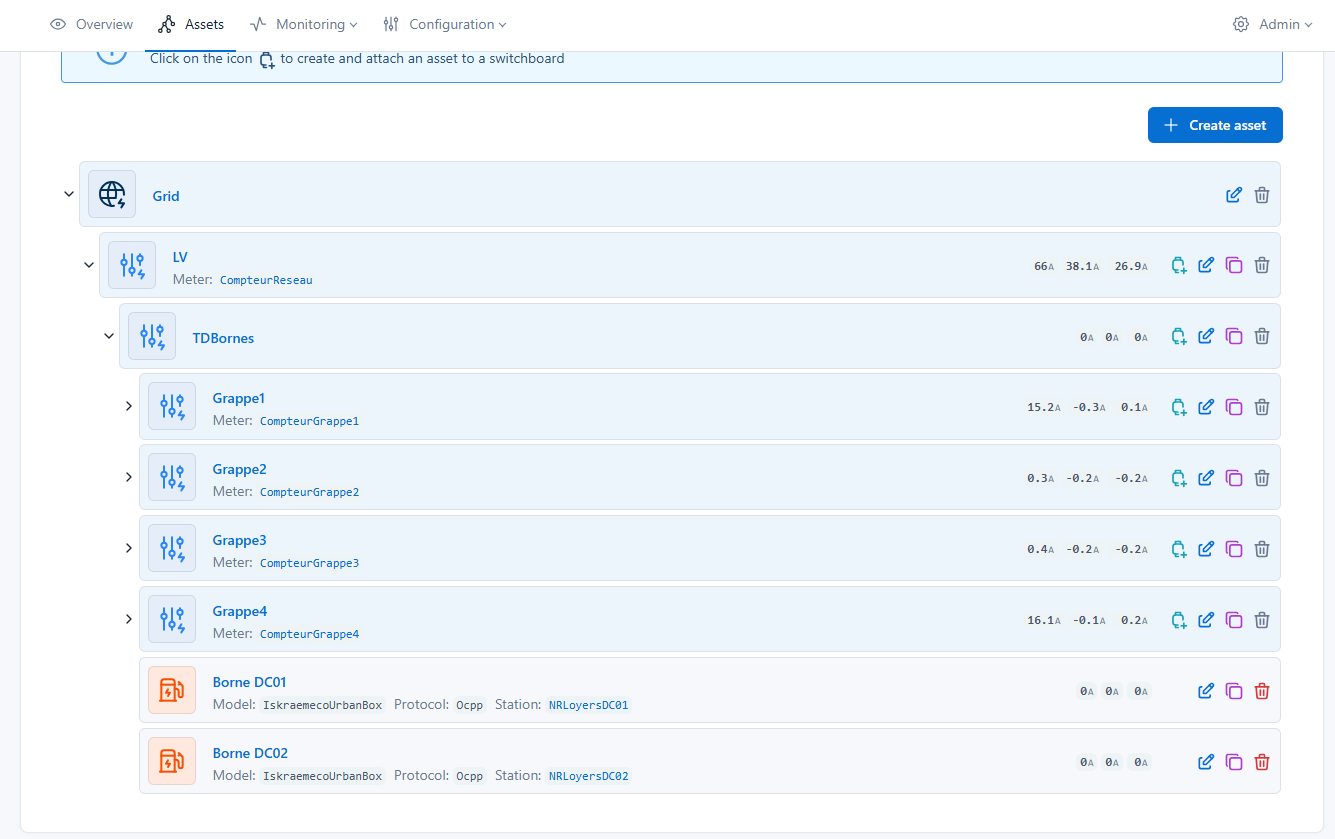
The topology represents the site's electrical organization.
It lets you structure equipment (charge points, meters, batteries, photovoltaics…) and define their connections to guarantee reliable energy calculations and efficient smart charging.
🚀 Access
- Open a site
- Go to Assets
- Click on the Topology tab
🧭 Overview
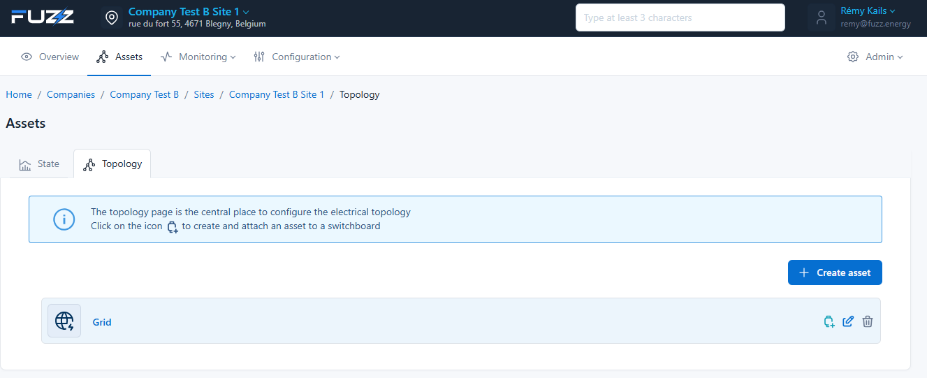
The topology page is the central place to:
- Visualize the electrical structure
- Add and organize assets
- Define relationships between equipment
🌐 Structure
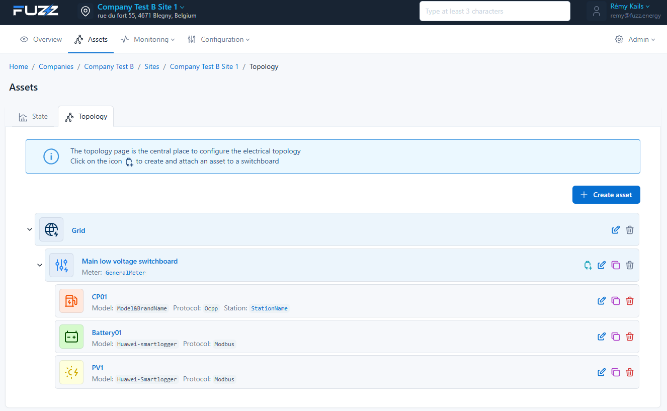
The topology follows an electrical hierarchy:
Grid
└── Switchboard
    └── Assets (charge points, batteries, PV, meters…)
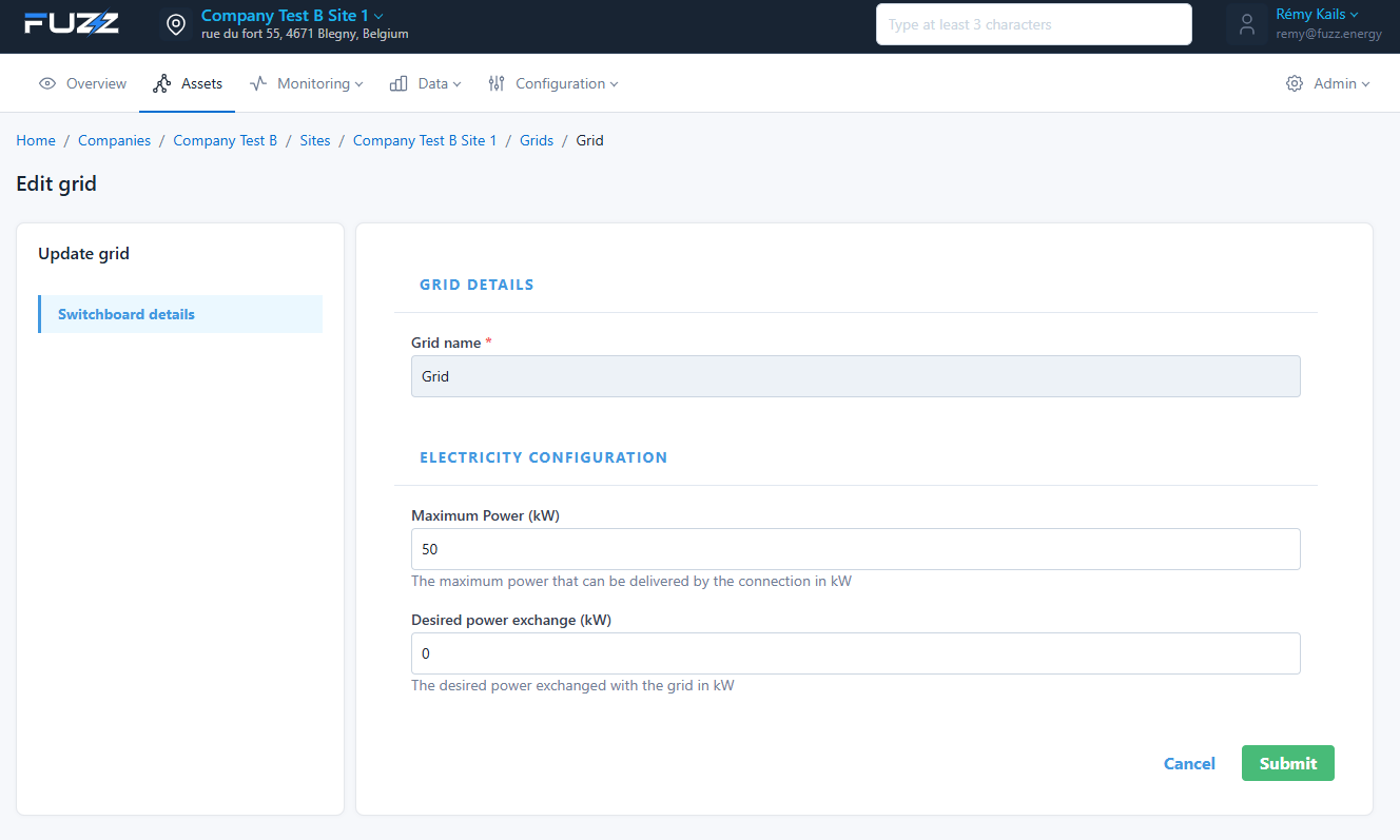
⚡ Grid
- Entry point of the electrical grid
- Mandatory root element
- The GridTarget lets you define the target power of batteries operating in this mode
- The grid's maximum power enables peak shaving on the client's site.
🔌 Switchboard
- Electrical panel
- Lets you group equipment
🔋 Assets
- Charge points
- Meters
- Batteries
- Photovoltaics
- Fridges
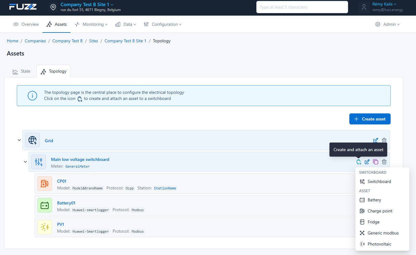
➕ Adding an asset
Click on + Create asset
Then choose the asset type:
- Switchboard
- Charge point
- Meter
- Battery
- Photovoltaic
🔌 Creating the main switchboard
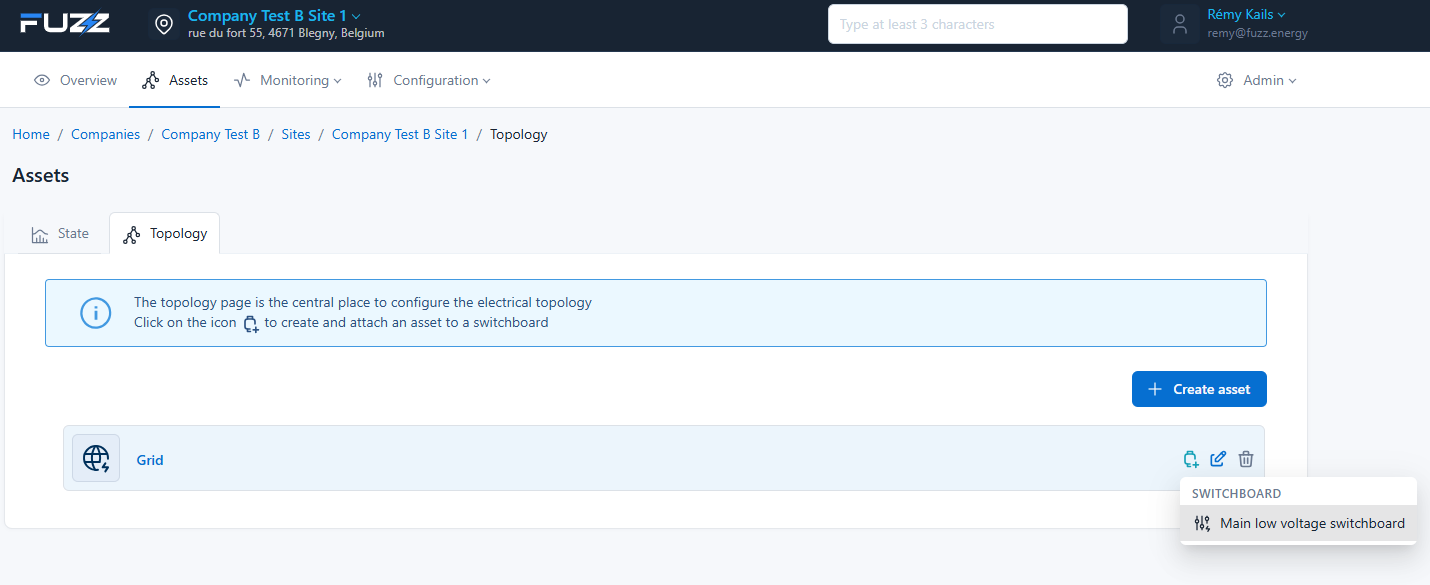
The first step in configuring the topology is to create the main switchboard:
👉 Main low voltage switchboard
⚠️ Important point
- This switchboard is the only asset directly connected to the Grid
- All other equipment will be attached to this switchboard (or to its children)
Grid
└── Main low voltage switchboard
    └── Other assets
🎯 Role
The Main low voltage switchboard:
- represents the site's main distribution point
- serves as the root for the entire electrical topology
- centralizes measurements and power distribution
There is only one switchboard connected to the Grid.
🔌 Creating a secondary switchboard
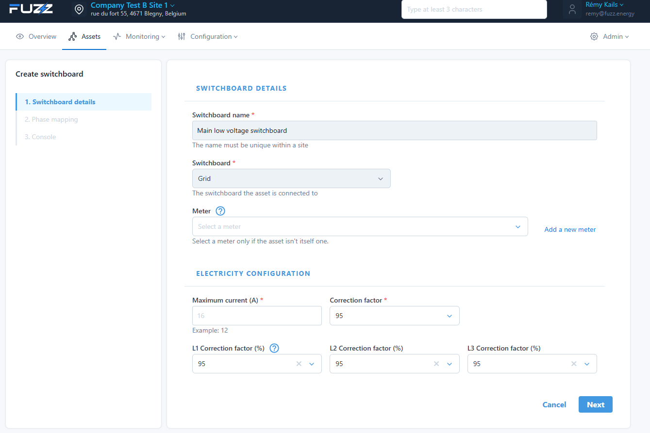
Steps:
- Switchboard details
- Phase mapping
- Console access: to access the local web page of a device linked to the "Switchboard"
⚙️ Phase mapping
Lets you assign phases:
- L1 / L2 / L3
- Current inversion possible
👉 Critical for the consistency of electrical measurements
⚡ Creating a charge point
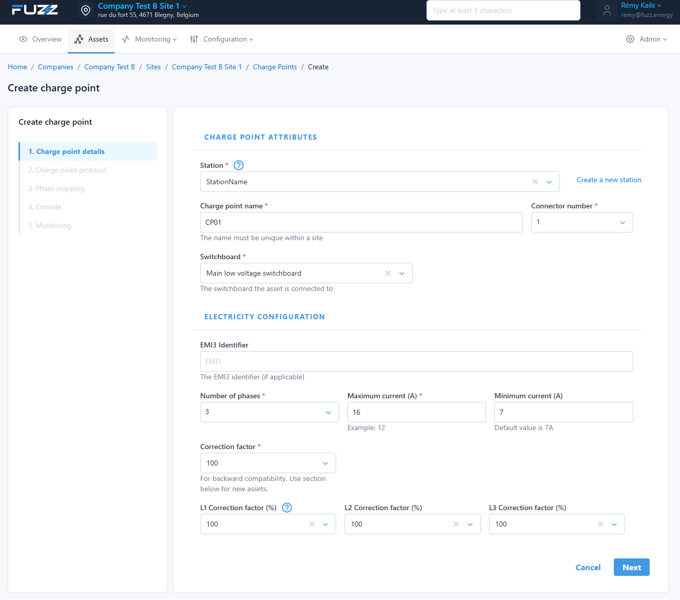
Steps:
- Charge point details
- Protocol (OCPP)
- Phase mapping
- Console access
- Monitoring
Key points:
- Association with a station
- Attachment to a switchboard
- Configuration of currents (min/max)
🔌 Protocol
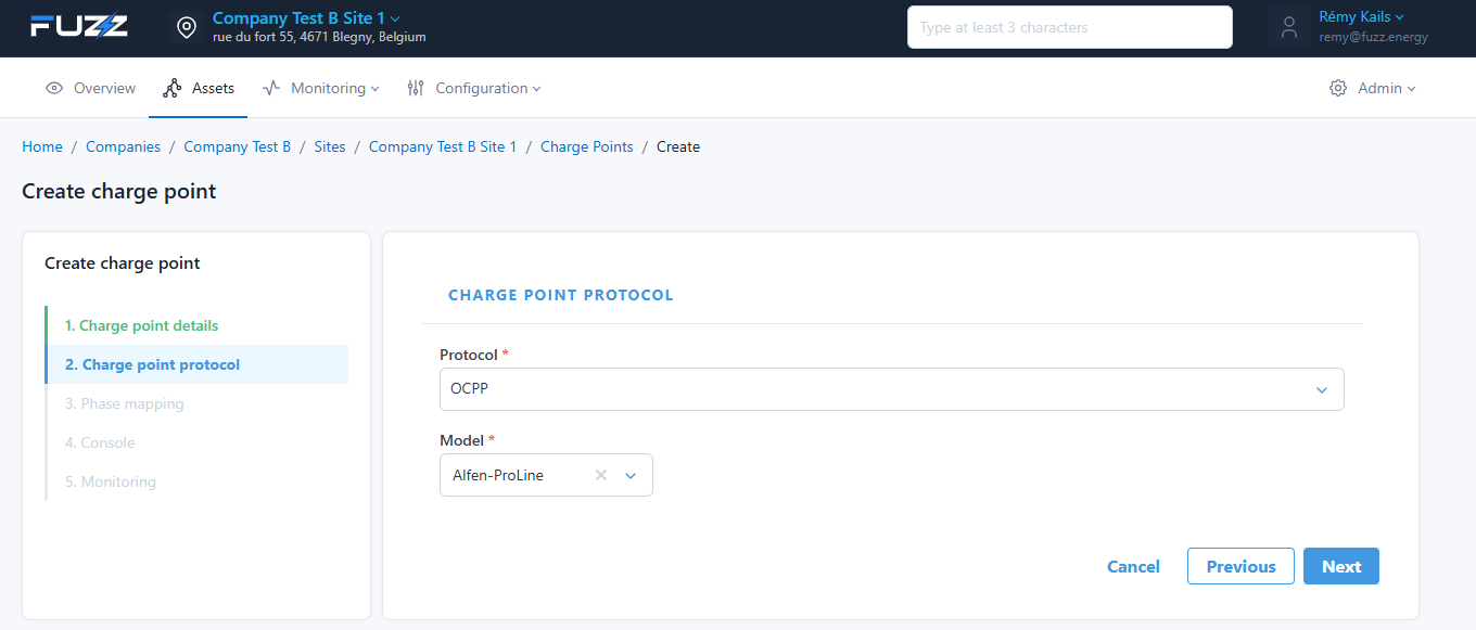
- OCPP or Modbus TCP or Modbus RTU
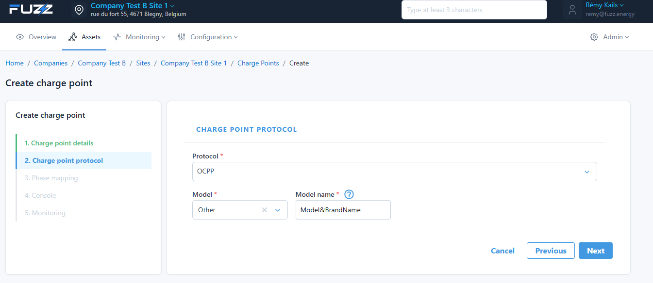
- Charge point model
If the model is not in the list, an OCPP charge point can use the OCPP1.6 protocol and a standard configuration by selecting "Other"
🔋 Creating a battery
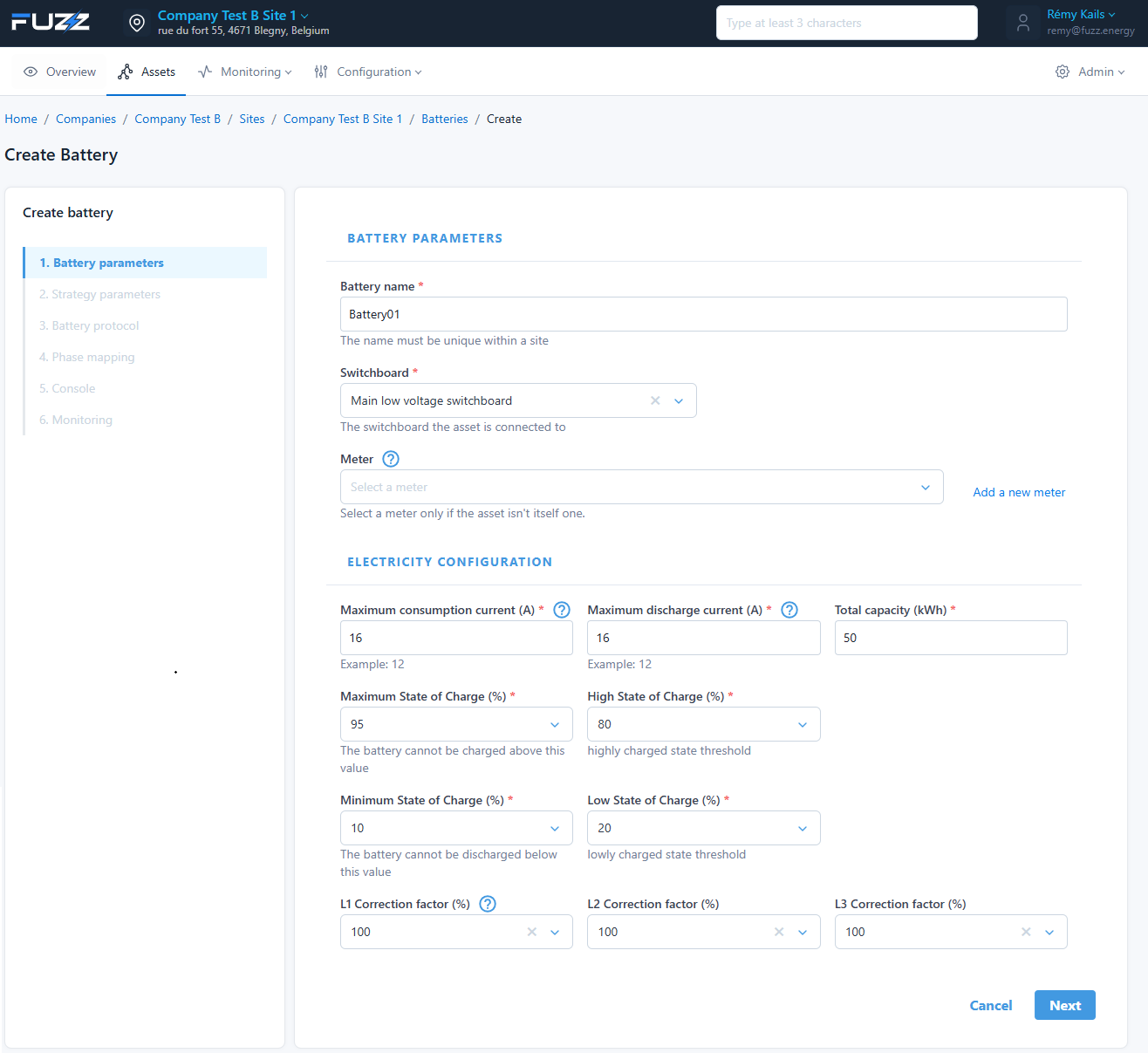
Settings:
- Capacity (kWh)
- Max charge / discharge current
- State of charge (min / low / high / max)
🔋 State of Charge (SoC) management
The battery is controlled with 4 SoC thresholds:
- Maximum SoC (%) → upper limit (e.g.: 95%)
- High SoC (%) → charge slowdown threshold
- Low SoC (%) → discharge slowdown threshold
- Minimum SoC (%) → lower limit (e.g.: 10%)
⚙️ Operation
🔼 Upper zone (charging)
Between High SoC and Maximum SoC:
- Charging power is progressively reduced
- In a linear way:
- at High SoC → charging not limited
- at Maximum SoC → charging = 0 kW
👉 The battery naturally slows down before reaching its limit.
🔽 Lower zone (discharging)
Between Low SoC and Minimum SoC:
- Discharge power is progressively reduced
- In a linear way:
- at Low SoC → discharging not limited
- at Minimum SoC → discharging = 0 kW
👉 The battery avoids draining abruptly.
🎯 Why this mechanism?
Without these intermediate thresholds:
- charging or discharging would stop abruptly at min/max
- this would create consumption or production peaks
- negative impact on:
- the grid
- smart charging
- site stability
- quarter-hourly peak
✅ Benefits
- Progressive and stable transition
- Reduction of electrical peaks
- Better grid integration
💡 Best practices
- Keep a margin between:
- High and Max (e.g.: 80% → 95%)
- Low and Min (e.g.: 25% → 10%)
- Avoid thresholds that are too close → otherwise an "on/off" effect
🎯 Strategy
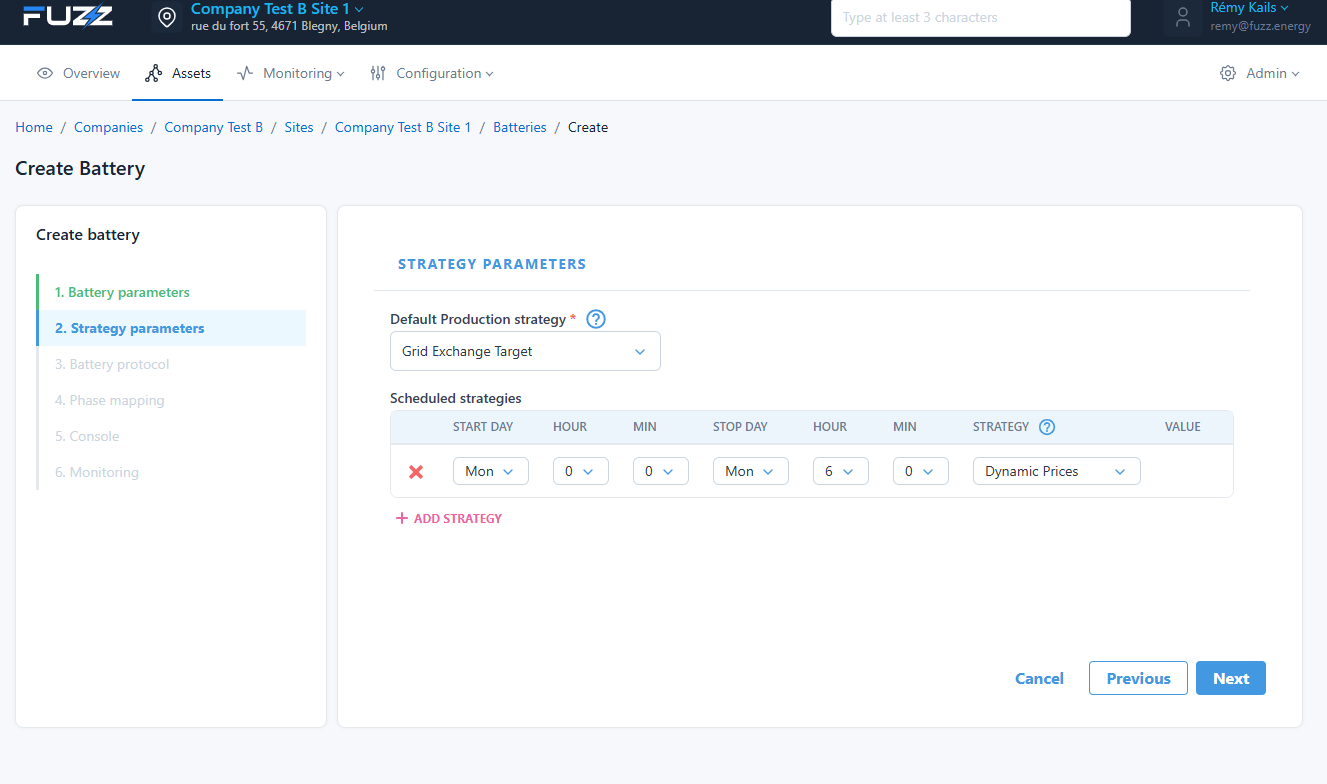
- Default strategy
- Hourly scheduling
When the GridTarget strategy is chosen, the target value exchanged with the grid is configurable by editing the "Grid" in the topology.
☀️ Creating a photovoltaic
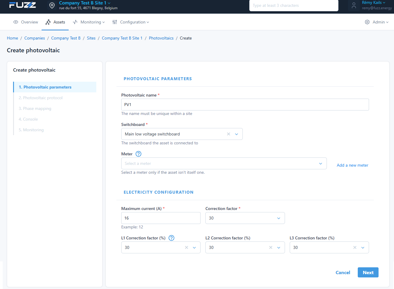
Settings:
- Maximum power
- Correction factors
- Association with a switchboard
📊 Creating a meter
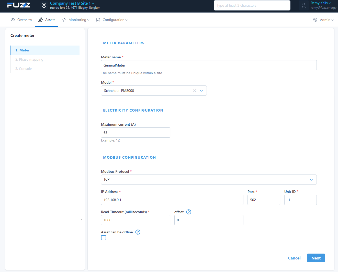
Configuration:
- Model
- Modbus communication
- IP address / port
Meters can be linked to other types of assets (Switchboard, Photovoltaic, etc.). Meters are not directly included in the topology but are linked to other assets. The most common case is a meter linked to the main low-voltage switchboard to measure the exchange with the grid.
🔗 Console: Asset local web page
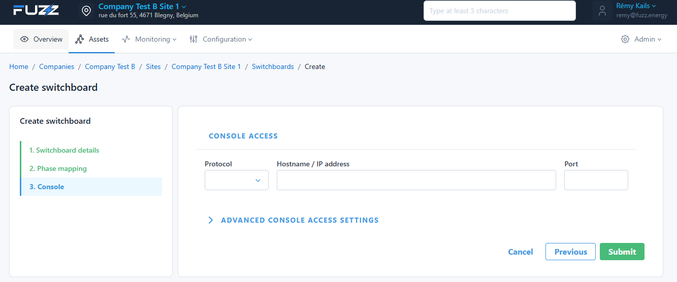
Lets you access a device's local interface:
- Protocol: http or https
- IP / hostname
- Port: by default the web page port is 80 over http and 443 over https
⚙️ Advanced settings
- Override host / referer
- Force HTTP
- Base path
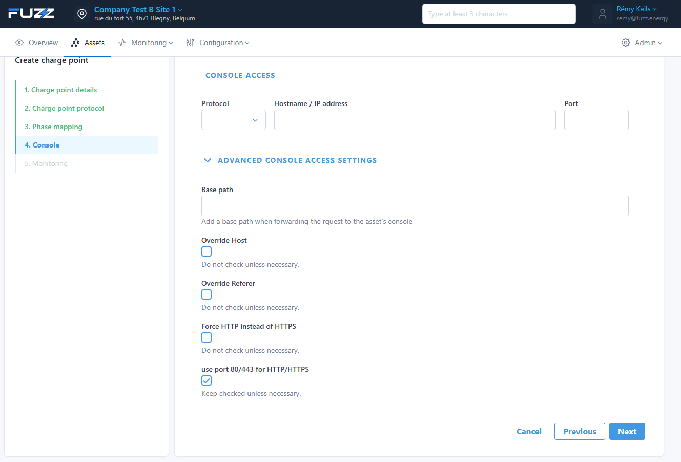
✅ Result